
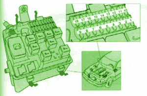
2006 Volvo XC Series Main Fuse Box Diagram
2006 Volvo XC Series Main Fuse Box Map
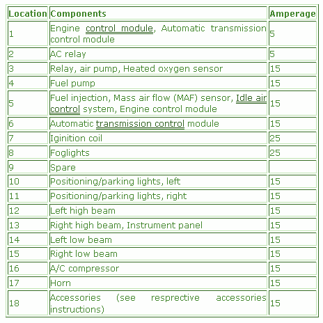
Fuse Panel Layout Diagram Parts: Mass air flow sensor, Idle air control system, Fog lights, Positioning/parking lights, , Positioning/parking lights, right, Left high beam, Right high beam, Instrument panel, Engine control module, Automatic transmission control module, Ignition coil, Relay, air pump, Heated oxygen sensor, Engine control module, Automatic transmission control module, Fuel injection, Left low beam, Right low beam, A/C compressor, Horn, Accessories.
