Tag: Idle air control system

2001 Volvo 960 Fuse BOx Diagram

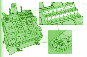
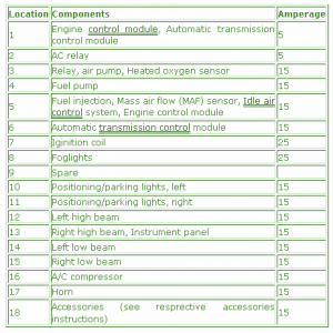
2001 Volvo 960 Fuse BOx Diagram 2001 Volvo 960 Fuse BOx Map Fuse Panel Layout Diagram Parts: Positioning/parking lights, , Positioning/parking lights, right, Left high beam , Right high beam, Instrument panel, Left low beam, Right low beam, A/C compressor, Horn, Accessories (see resprective accessories instructions), Relay, air pump, Heated oxygen sensor, Engine control module, …

Continue reading

1997 Volvo 850 Fuse Box Diagram

1997 Volvo 850 Fuse Box Diagram 1997 Volvo 850 Fuse Box Map Fuse Panel Layout Diagram Parts: Right high beam, Instrument panel, Engine control module, Automatic transmission control module, Ignition coil, Relay, air pump, Heated oxygen sensor, Engine control module, Automatic transmission control module, Fuel injection, Left low beam, Right low beam, A/C compressor, Horn, …

Continue reading

1996 Volvo 960 Fuse BOx Diagram

1996 Volvo 960 Fuse BOx Diagram 1996 Volvo 960 Fuse BOx Map Fuse Panel Layout Diagram Parts: Relay, air pump, Heated oxygen sensor, Engine control module, Automatic transmission control module, Fuel injection, Mass air flow (MAF) sensor, Idle air control system, Engine control module, Automatic transmission control module, Iginition coil, Foglights, Positioning/parking lights, , Positioning/parking …

Continue reading